Technology
Absolute Measurement: Eliminating the Need for CMM Correlation Studies
So far, the vision inspection systems have been tethered to CMM correlation studies. We say no more!
Eliminating CMM correlation studies requires a new way of verifying the results. In this article, we explain the verification process in accordance with the required standards.
In my previous article, we introduced the concept of Absolute Measurement and CAD programming for the Mapvision Q inspection system. Before we get to the results with real production parts, we need to verify that the measured coordinates really are absolute. How did we do that? Read on to find out.
To prove that the coordinates measured by Mapvision Q are in fact absolute, a verification method must be introduced. The VDI 2634-1 recommendation is the one best suited for camera-based measuring system verification.
A simulator component has been developed to automate the selection of seven distinct measuring artefact positions for every pairing of Mapvision Q and the measured part(s), following the VDI guidelines. The simulator selected positions are then recreated in the real environment using an AR-enhanced process involving a mechanical portal fixture with degrees of freedom limited to that of the simulated world to minimize operator influence.
Measured distance combinations between the targets on the artefact are then compared to ground truth values known with a maximum of 5.8 µm uncertainty. The combination of simulation tools and flexible mechanics allows the absolute accuracy verification method to be implemented in negligible time as a part of the delivery process of every Mapvision Q.
A thorough test procedure like this is only required one time at Mapvision premises before shipping the unit. It practically verifies the design of the sensor configuration, which does not change over the lifetime of the system.
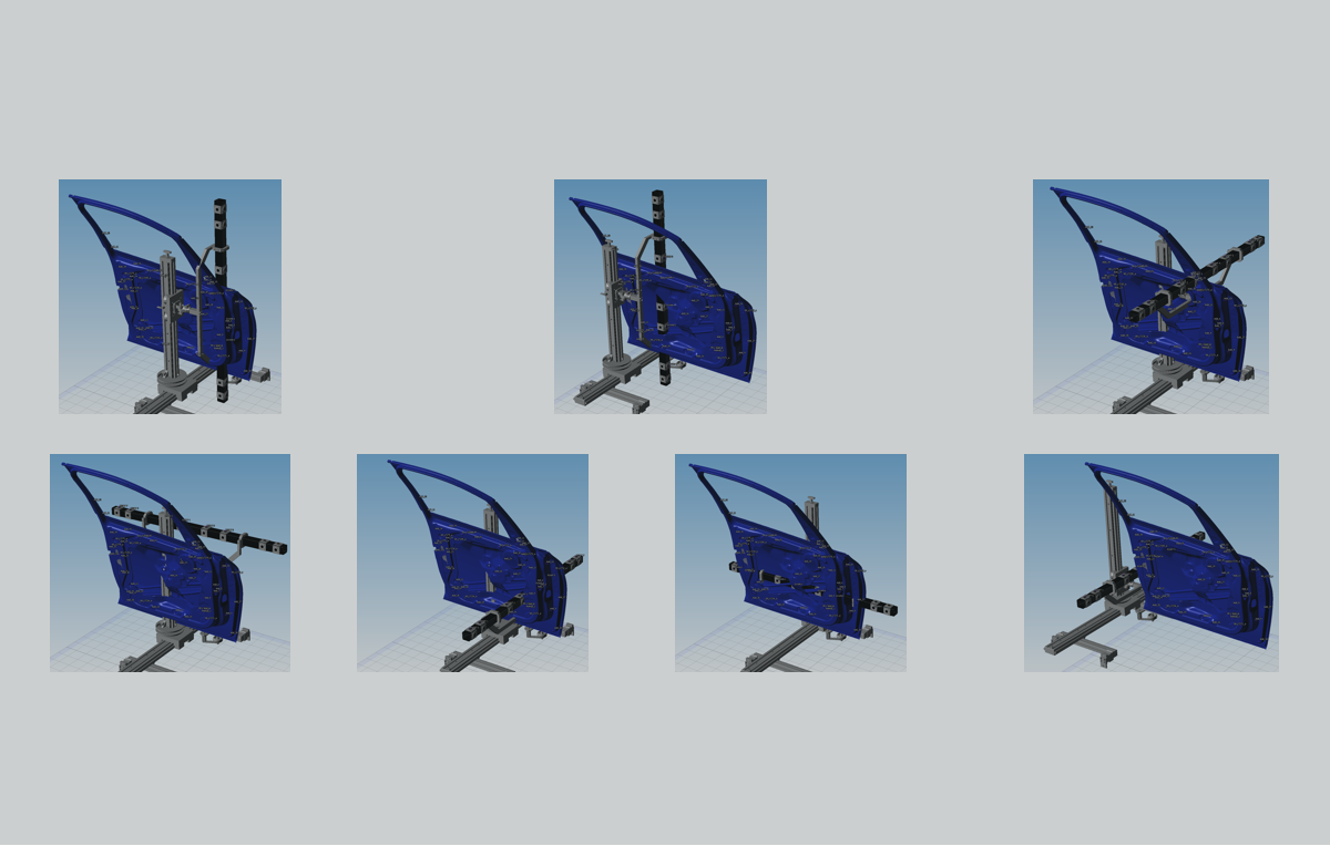
The images below show the artefact positions that were automatically selected in a VDI 2634-1 compliant simulation for a door part.
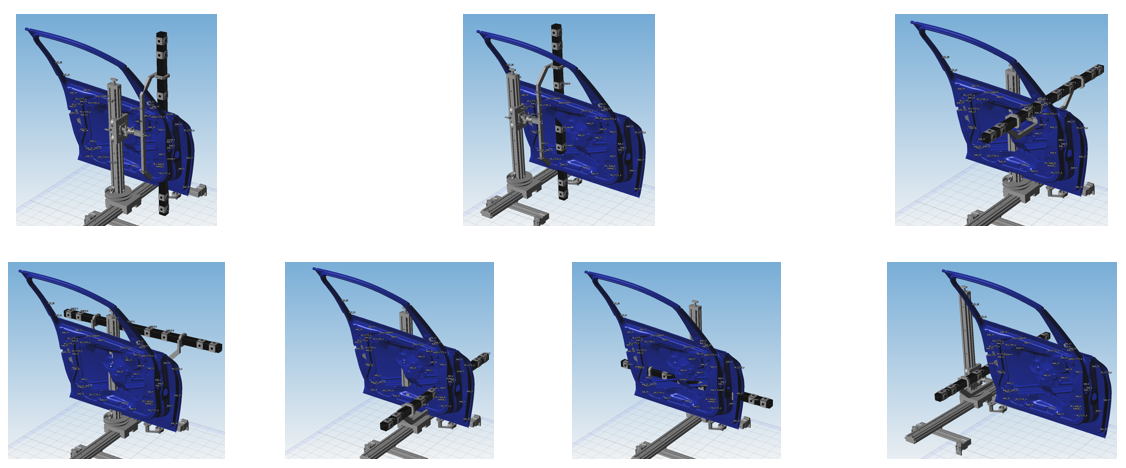 Figure 1:The seven positions of the VDI artefact selected by simulation.
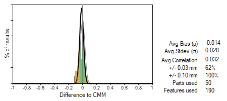
Testing with the door part, the results indicate that the absolute accuracy of the tested Mapvision Quality Gate does not have significant bias (-0.014 mm). The standard deviation of the distribution of errors is 0.028 mm, which implies the error falls under 0.1 mm with 99.7% confidence (±3σ). The maximum error in the dataset was 0.089 mm and the average correlation to the CMM values was 0.032 mm.
It was also apparent from the data set that the length measuring error does not increase along with the tested length, as is the case with robots and other mechanical measuring solutions. This is a very promising aspect for the Mapvision Quality Gate to scale the absolute measuring capability to parts of different shapes and sizes.
Figure 2 shows the distribution of the errors and a summary of the distribution parameters.
In our next article, we demonstrate the results from a real car part. Check it out!
So far, the vision inspection systems have been tethered to CMM correlation studies. We say no more!
Sampling and statistical process controls fall short to satisfy the customer demand for lower and lower parts per million (PPM) in high-volume,...
You can now program and deploy quality inspection in minutes without having to go to the CMM. That is what Mapvision Absolute Measurement means in...